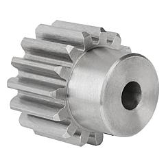
Product Description
SPROCKET 1/2” X 5/16” 08B SERIES SPROCKETS
| For Chain Acc.to DIN8187 ISO/R 606 | |||||
| Tooth Radius r3 | 13.0mm | ||||
| Radius Width C | 1.3mm | ||||
| Tooth Width b1 | 7.0mm | ||||
| Tooth Width B1 | 7.2mm | ||||
| Tooth Width B2 | 21.0mm | ||||
| Tooth Width B3 | 34.9mm | ||||
| 08B SERIES ROLLER CHAINS | |||||
| Pitch | 12.7 mm | ||||
| Internal Width | 7.75 mm | ||||
| Roller Diameter | 8.51 mm | ||||
| Z | de | dp | SIMPLEX | DUPLEX | TRIPLEX |
| D1 | D2 | D3 | |||
| 8 | 37.2 | 33.18 | 8 | 10 | 10 |
| 9 | 41.0 | 37.13 | 8 | 10 | 10 |
| 10 | 45.2 | 41.10 | 8 | 10 | 10 |
| 11 | 48.7 | 45.07 | 10 | 10 | 12 |
| 12 | 53.0 | 49.07 | 10 | 10 | 12 |
| 13 | 57.4 | 53.06 | 10 | 10 | 12 |
| 14 | 61.8 | 57.07 | 10 | 10 | 12 |
| 15 | 65.5 | 61.09 | 10 | 10 | 12 |
| 16 | 69.5 | 65.10 | 10 | 12 | 16 |
| 17 | 73.6 | 69.11 | 10 | 12 | 16 |
| 18 | 77.8 | 73.14 | 10 | 12 | 16 |
| 19 | 81.7 | 77.16 | 10 | 12 | 16 |
| 20 | 85.8 | 81.19 | 10 | 12 | 16 |
| 21 | 89.7 | 85.22 | 12 | 16 | 16 |
| 22 | 93.8 | 89.24 | 12 | 16 | 16 |
| 23 | 98.2 | 93.27 | 12 | 16 | 16 |
| 24 | 101.8 | 97.29 | 12 | 16 | 16 |
| 25 | 105.8 | 101.33 | 12 | 16 | 16 |
| 26 | 110.0 | 105.36 | 16 | 16 | 16 |
| 27 | 114.0 | 109.40 | 16 | 16 | 16 |
| 28 | 118.0 | 113.42 | 16 | 16 | 16 |
| 29 | 122.0 | 117.46 | 16 | 16 | 16 |
| 30 | 126.1 | 121.50 | 16 | 16 | 16 |
| 31 | 130.2 | 125.54 | 16 | 16 | 20 |
| 32 | 134.3 | 129.56 | 16 | 16 | 20 |
| 33 | 138.4 | 133.60 | 16 | 16 | 20 |
| 34 | 142.6 | 137.64 | 16 | 16 | 20 |
| 35 | 146.7 | 141.68 | 16 | 16 | 20 |
| 36 | 151.0 | 145.72 | 16 | 20 | 20 |
| 37 | 154.6 | 149.76 | 16 | 20 | 20 |
| 38 | 158.6 | 153.80 | 16 | 20 | 20 |
| 39 | 162.7 | 157.83 | 16 | 20 | 20 |
| 40 | 166.8 | 161.87 | 16 | 20 | 20 |
| 41 | 171.4 | 165.91 | 20 | 20 | 25 |
| 42 | 175.4 | 169.94 | 20 | 20 | 25 |
| 43 | 179.7 | 173.98 | 20 | 20 | 25 |
| 44 | 183.8 | 178.02 | 20 | 20 | 25 |
| 45 | 188.0 | 182.07 | 20 | 20 | 25 |
| 46 | 192.1 | 186.10 | 20 | 20 | 25 |
| 47 | 196.2 | 190.14 | 20 | 20 | 25 |
| 48 | 200.3 | 194.18 | 20 | 20 | 25 |
| 49 | 204.3 | 198.22 | 20 | 20 | 25 |
| 50 | 208.3 | 202.26 | 20 | 20 | 25 |
| 51 | 212.1 | 206.30 | 20 | 25 | 25 |
| 52 | 216.1 | 210.34 | 20 | 25 | 25 |
| 53 | 220.2 | 214.37 | 20 | 25 | 25 |
| 54 | 224.1 | 218.43 | 20 | 25 | 25 |
| 55 | 228.1 | 222.46 | 20 | 25 | 25 |
| 56 | 232.2 | 226.50 | 20 | 25 | 25 |
| 57 | 236.4 | 230.54 | 20 | 25 | 25 |
| 58 | 240.5 | 234.58 | 20 | 25 | 25 |
| 59 | 244.5 | 238.62 | 20 | 25 | 25 |
| 60 | 248.6 | 242.66 | 20 | 25 | 25 |
| 62 | 256.9 | 250.74 | 25 | 25 | 25 |
| 64 | 265.1 | 258.82 | 25 | 25 | 25 |
| 65 | 269.0 | 262.86 | 25 | 25 | 25 |
| 66 | 273.0 | 266.91 | 25 | 25 | 25 |
| 68 | 281.0 | 274.99 | 25 | 25 | 25 |
| 70 | 289.0 | 283.07 | 25 | 25 | 25 |
| 72 | 297.2 | 291.15 | 25 | 25 | 25 |
| 75 | 309.2 | 303.28 | 25 | 25 | 25 |
| 76 | 313.2 | 307.32 | 25 | 25 | 25 |
| 78 | 321.4 | 315.40 | 25 | 25 | 25 |
| 80 | 329.4 | 323.49 | 25 | 25 | 25 |
| 85 | 349.0 | 343.69 | 25 | 25 | 25 |
| 90 | 369.9 | 363.90 | 25 | 25 | 25 |
| 95 | 390.1 | 384.11 | 25 | 25 | 25 |
| 100 | 410.3 | 404.32 | 25 | 25 | 25 |
| 110 | 450.7 | 444.74 | 25 | 25 | 25 |
| 114 | 466.9 | 460.91 | 25 | 25 | 25 |
| 120 | 491.2 | 485.16 | 25 | 25 | 25 |
| 125 | 511.3 | 505.37 | 25 | 25 | 25 |
BASIC INFO.
|
Type: |
Simplex, Duplex, Triplex |
|
Sprocket Model: |
3/8″,1/2″,5/8″,3/4″,1″,1.25″,1.50″,1.75″,2.00″,2.25″,2.00″,2.25″,2.50″, 3″ |
|
Teeth Number: |
9-100 |
|
Standard: |
ANSI , JIS, DIN, ISO |
|
Material: |
1571, 1045, SS304 , SS316; As Per User Request. |
|
Performance Treatment: |
Carburizing, High Frequency Treatment, Hardening and Tempering, Nitriding |
|
Surface Treatment: |
Black of Oxidation, Zincing, Nickelage. |
| Characteristic | Fire Resistant, Oil Resistant, Heat Resistant, CHINAMFG resistance, Oxidative resistance, Corrosion resistance, etc |
| Design criterion | ISO DIN ANSI & Customer Drawings |
| Application | Industrial transmission equipment |
| Package | Wooden Case / Container and pallet, or made-to-order |
|
Certification: |
ISO9001 SGS |
|
Quality Inspection: |
Self-check and Final-check |
|
Sample: |
ODM&OEM, Trial Order Available and Welcome |
| Advantage | Quality first, Service first, Competitive price, Fast delivery |
| Delivery Time | 10 days for samples. 15 days for official order. |
INSTALLATION AND USING
The chain spocket, as a drive or deflection for chains, has pockets to hold the chain links with a D-profile cross section with flat side surfaces parallel to the centre plane of the chain links, and outer surfaces at right angles to the chain link centre plane. The chain links are pressed firmly against the outer surfaces and each of the side surfaces by the angled laying surfaces at the base of the pockets, and also the support surfaces of the wheel body together with the end sides of the webs formed by the leading and trailing walls of the pocket.
NOTICE
When fitting new chainwheels it is very important that a new chain is fitted at the same time, and vice versa. Using an old chain with new sprockets, or a new chain with old sprockets will cause rapid wear.
It is important if you are installing the chainwheels yourself to have the factory service manual specific to your model. Our chainwheels are made to be a direct replacement for your OEM chainwheels and as such, the installation should be performed according to your models service manual.
During use a chain will stretch (i.e. the pins will wear causing extension of the chain). Using a chain which has been stretched more than the above maximum allowance causes the chain to ride up the teeth of the sprocket. This causes damage to the tips of the chainwheels teeth, as the force transmitted by the chain is transmitted entirely through the top of the tooth, rather than the whole tooth. This results in severe wearing of the chainwheel.
FOR CHAIN STHangZhouRDS
Standards organizations (such as ANSI and ISO) maintain standards for design, dimensions, and interchangeability of transmission chains. For example, the following Table shows data from ANSI standard B29.1-2011 (Precision Power Transmission Roller Chains, Attachments, and Sprockets) developed by the American Society of Mechanical Engineers (ASME). See the references[8][9][10] for additional information.
ASME/ANSI B29.1-2011 Roller Chain Standard SizesSizePitchMaximum Roller DiameterMinimum Ultimate Tensile StrengthMeasuring Load25
| ASME/ANSI B29.1-2011 Roller Chain Standard Sizes | ||||
| Size | Pitch | Maximum Roller Diameter | Minimum Ultimate Tensile Strength | Measuring Load |
|---|---|---|---|---|
| 25 | 0.250 in (6.35 mm) | 0.130 in (3.30 mm) | 780 lb (350 kg) | 18 lb (8.2 kg) |
| 35 | 0.375 in (9.53 mm) | 0.200 in (5.08 mm) | 1,760 lb (800 kg) | 18 lb (8.2 kg) |
| 41 | 0.500 in (12.70 mm) | 0.306 in (7.77 mm) | 1,500 lb (680 kg) | 18 lb (8.2 kg) |
| 40 | 0.500 in (12.70 mm) | 0.312 in (7.92 mm) | 3,125 lb (1,417 kg) | 31 lb (14 kg) |
| 50 | 0.625 in (15.88 mm) | 0.400 in (10.16 mm) | 4,880 lb (2,210 kg) | 49 lb (22 kg) |
| 60 | 0.750 in (19.05 mm) | 0.469 in (11.91 mm) | 7,030 lb (3,190 kg) | 70 lb (32 kg) |
| 80 | 1.000 in (25.40 mm) | 0.625 in (15.88 mm) | 12,500 lb (5,700 kg) | 125 lb (57 kg) |
| 100 | 1.250 in (31.75 mm) | 0.750 in (19.05 mm) | 19,531 lb (8,859 kg) | 195 lb (88 kg) |
| 120 | 1.500 in (38.10 mm) | 0.875 in (22.23 mm) | 28,125 lb (12,757 kg) | 281 lb (127 kg) |
| 140 | 1.750 in (44.45 mm) | 1.000 in (25.40 mm) | 38,280 lb (17,360 kg) | 383 lb (174 kg) |
| 160 | 2.000 in (50.80 mm) | 1.125 in (28.58 mm) | 50,000 lb (23,000 kg) | 500 lb (230 kg) |
| 180 | 2.250 in (57.15 mm) | 1.460 in (37.08 mm) | 63,280 lb (28,700 kg) | 633 lb (287 kg) |
| 200 | 2.500 in (63.50 mm) | 1.562 in (39.67 mm) | 78,175 lb (35,460 kg) | 781 lb (354 kg) |
| 240 | 3.000 in (76.20 mm) | 1.875 in (47.63 mm) | 112,500 lb (51,000 kg) | 1,000 lb (450 kg |
For mnemonic purposes, below is another presentation of key dimensions from the same standard, expressed in fractions of an inch (which was part of the thinking behind the choice of preferred numbers in the ANSI standard):
| Pitch (inches) | Pitch expressed in eighths |
ANSI standard chain number |
Width (inches) |
|---|---|---|---|
| 1⁄4 | 2⁄8 | 25 | 1⁄8 |
| 3⁄8 | 3⁄8 | 35 | 3⁄16 |
| 1⁄2 | 4⁄8 | 41 | 1⁄4 |
| 1⁄2 | 4⁄8 | 40 | 5⁄16 |
| 5⁄8 | 5⁄8 | 50 | 3⁄8 |
| 3⁄4 | 6⁄8 | 60 | 1⁄2 |
| 1 | 8⁄8 | 80 | 5⁄8 |
Notes:
1. The pitch is the distance between roller centers. The width is the distance between the link plates (i.e. slightly more than the roller width to allow for clearance).
2. The right-hand digit of the standard denotes 0 = normal chain, 1 = lightweight chain, 5 = rollerless bushing chain.
3. The left-hand digit denotes the number of eighths of an inch that make up the pitch.
4. An “H” following the standard number denotes heavyweight chain. A hyphenated number following the standard number denotes double-strand (2), triple-strand (3), and so on. Thus 60H-3 denotes number 60 heavyweight triple-strand chain.
A typical bicycle chain (for derailleur gears) uses narrow 1⁄2-inch-pitch chain. The width of the chain is variable, and does not affect the load capacity. The more sprockets at the rear wheel (historically 3-6, nowadays 7-12 sprockets), the narrower the chain. Chains are sold according to the number of speeds they are designed to work with, for example, “10 speed chain”. Hub gear or single speed bicycles use 1/2″ x 1/8″ chains, where 1/8″ refers to the maximum thickness of a sprocket that can be used with the chain.
Typically chains with parallel shaped links have an even number of links, with each narrow link followed by a broad one. Chains built up with a uniform type of link, narrow at 1 and broad at the other end, can be made with an odd number of links, which can be an advantage to adapt to a special chainwheel-distance; on the other side such a chain tends to be not so strong.
Roller chains made using ISO standard are sometimes called as isochains.
WHY CHOOSE US
1. Reliable Quality Assurance System
2. Cutting-Edge Computer-Controlled CNC Machines
3. Bespoke Solutions from Highly Experienced Specialists
4. Customization and OEM Available for Specific Application
5. Extensive Inventory of Spare Parts and Accessories
6. Well-Developed CHINAMFG Marketing Network
7. Efficient After-Sale Service System
The 219 sets of advanced automatic production equipment provide guarantees for high product quality. The 167 engineers and technicians with senior professional titles can design and develop products to meet the exact demands of customers, and OEM customizations are also available with us. Our sound global service network can provide customers with timely after-sales technical services.
We are not just a manufacturer and supplier, but also an industry consultant. We work pro-actively with you to offer expert advice and product recommendations in order to end up with a most cost effective product available for your specific application. The clients we serve CHINAMFG range from end users to distributors and OEMs. Our OEM replacements can be substituted wherever necessary and suitable for both repair and new assemblies.
|
Shipping Cost:
Estimated freight per unit. |
To be negotiated |
|---|
| Standard Or Nonstandard: | Standard |
|---|---|
| Application: | Motor, Electric Cars, Motorcycle, Machinery, Marine, Toy, Agricultural Machinery, Car |
| Hardness: | Hardened Tooth Surface |
| Samples: |
US$ 0/Piece
1 Piece(Min.Order) | Order Sample |
|---|
| Customization: |
Available
| Customized Request |
|---|
What are the environmental considerations when using spur gears?
When using spur gears, there are several environmental considerations to keep in mind. Here’s a detailed explanation:
1. Lubrication:
Proper lubrication is essential for the efficient and reliable operation of spur gears. However, the choice of lubricant can have environmental implications. It is important to select lubricants that are environmentally friendly, such as biodegradable or non-toxic lubricants. These lubricants minimize the risk of contaminating soil, water, or air during gear operation or maintenance.
2. Material Selection:
The choice of gear materials can also have environmental implications. Opting for materials that are recyclable or made from recycled content can reduce the environmental impact associated with gear production and end-of-life disposal. Additionally, selecting materials with low toxicity and minimal environmental harm during their lifecycle is important for sustainable gear manufacturing.
3. Energy Efficiency:
Efficient gear design and operation contribute to energy conservation and decreased environmental impact. By optimizing gear design, tooth profiles, and lubrication, it is possible to minimize power losses and increase overall gear system efficiency. This, in turn, reduces energy consumption and the associated environmental footprint.
4. Noise and Vibration:
Spur gears can generate noise and vibration during operation, which can have environmental implications, especially in noise-sensitive or residential areas. Implementing noise reduction measures such as gear tooth profiling, proper lubrication, and noise dampening techniques can help minimize the environmental impact of gear-induced noise and vibration.
5. Maintenance and End-of-Life Disposal:
Proper maintenance practices play a crucial role in minimizing the environmental impact of spur gears. Regular inspection, cleaning, and lubrication can prolong gear life, reduce the need for replacements, and minimize waste generation. Additionally, when spur gears reach the end of their life cycle, it is important to dispose of them responsibly, considering recycling options and proper waste management practices.
6. Environmental Regulations and Compliance:
When using spur gears, it is crucial to stay informed about relevant environmental regulations and standards. Different regions or industries may have specific requirements regarding lubricants, materials, noise emissions, or waste disposal. Adhering to these regulations ensures compliance and minimizes the environmental impact of gear usage.
7. Life Cycle Assessment (LCA):
Conducting a life cycle assessment of spur gears helps evaluate their overall environmental impact. LCA considers the environmental implications of gear production, use, maintenance, and disposal. It provides insights into potential environmental hotspots, allowing for targeted improvements in gear design, material selection, and operational practices.
By considering these environmental considerations and adopting sustainable practices throughout the life cycle of spur gears, it is possible to minimize their environmental impact and promote more environmentally friendly gear systems.
How do you maintain and service a spur gear system?
Maintaining and servicing a spur gear system is crucial to ensure its optimal performance, longevity, and reliability. Here’s a detailed explanation of how to maintain and service a spur gear system:
- Regular Inspection: Perform regular inspections of the spur gear system to identify any signs of wear, damage, misalignment, or abnormal operating conditions. Inspect the gear teeth, shafts, bearings, and housing for any visible issues. Pay attention to unusual noises, vibrations, or changes in gear performance. Early detection of problems allows for timely intervention and prevents further damage.
- Cleaning: Keep the spur gear system clean by removing any dirt, debris, or contaminants that may accumulate on the gear surfaces or within the gear housing. Use appropriate cleaning methods such as brushing, wiping, or blowing with compressed air. Avoid using harsh chemicals that may damage the gear components or compromise lubrication.
- Lubrication: Ensure proper lubrication of the spur gear system as per the manufacturer’s recommendations. Regularly check the lubricant levels and condition. Monitor viscosity, contamination levels, and oxidation of the lubricant. Replenish or replace the lubricant as necessary to maintain optimal gear lubrication and protection against wear.
- Alignment Check: Periodically check the shaft alignment of the gear system to ensure proper alignment. Misaligned shafts can result in increased wear, noise, and reduced gear efficiency. Use alignment tools such as dial indicators or laser alignment systems to verify and adjust the shaft alignment if needed.
- Torque and Fastener Check: Check the torque of fasteners, including bolts, set screws, and retaining rings, to ensure they are properly tightened. Loose fasteners can lead to gear misalignment and compromised performance. Follow the manufacturer’s recommended torque values for the specific gear system components.
- Replacement of Worn Components: Over time, gear components such as gear teeth, bearings, or shafts may wear out or become damaged. Replace any worn or damaged components promptly to prevent further issues and maintain the gear system’s functionality. Use genuine replacement parts recommended by the gear manufacturer.
- Monitoring Operating Conditions: Monitor the operating conditions of the gear system, including temperature, load, and speed. Ensure that the gear system operates within the specified limits and does not exceed the design parameters. Excessive heat, overloading, or high-speed operation can accelerate wear and reduce gear life.
- Training and Expert Support: Ensure that personnel responsible for maintaining and servicing the spur gear system receive proper training and have access to expert support. Familiarize yourself with the gear system’s documentation, including maintenance manuals, technical specifications, and troubleshooting guides. Consult with gear manufacturers or specialists for guidance on specific maintenance procedures or complex issues.
Developing a regular maintenance schedule and keeping accurate records of maintenance activities can help ensure consistent and effective servicing of the spur gear system. Adhering to recommended maintenance practices and addressing any identified issues promptly will help optimize the performance, reliability, and service life of the gear system.
It’s important to note that maintenance and servicing procedures may vary depending on the specific gear system, application, and manufacturer’s recommendations. Therefore, always refer to the gear system’s documentation and consult with the manufacturer for detailed maintenance instructions.
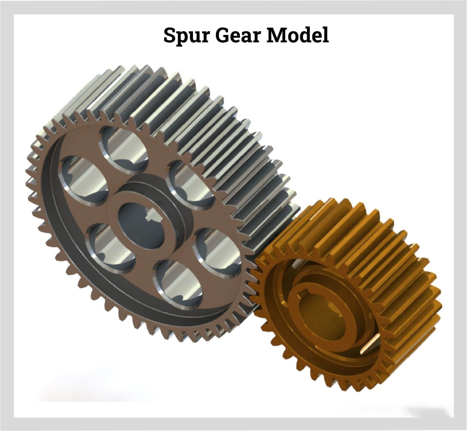
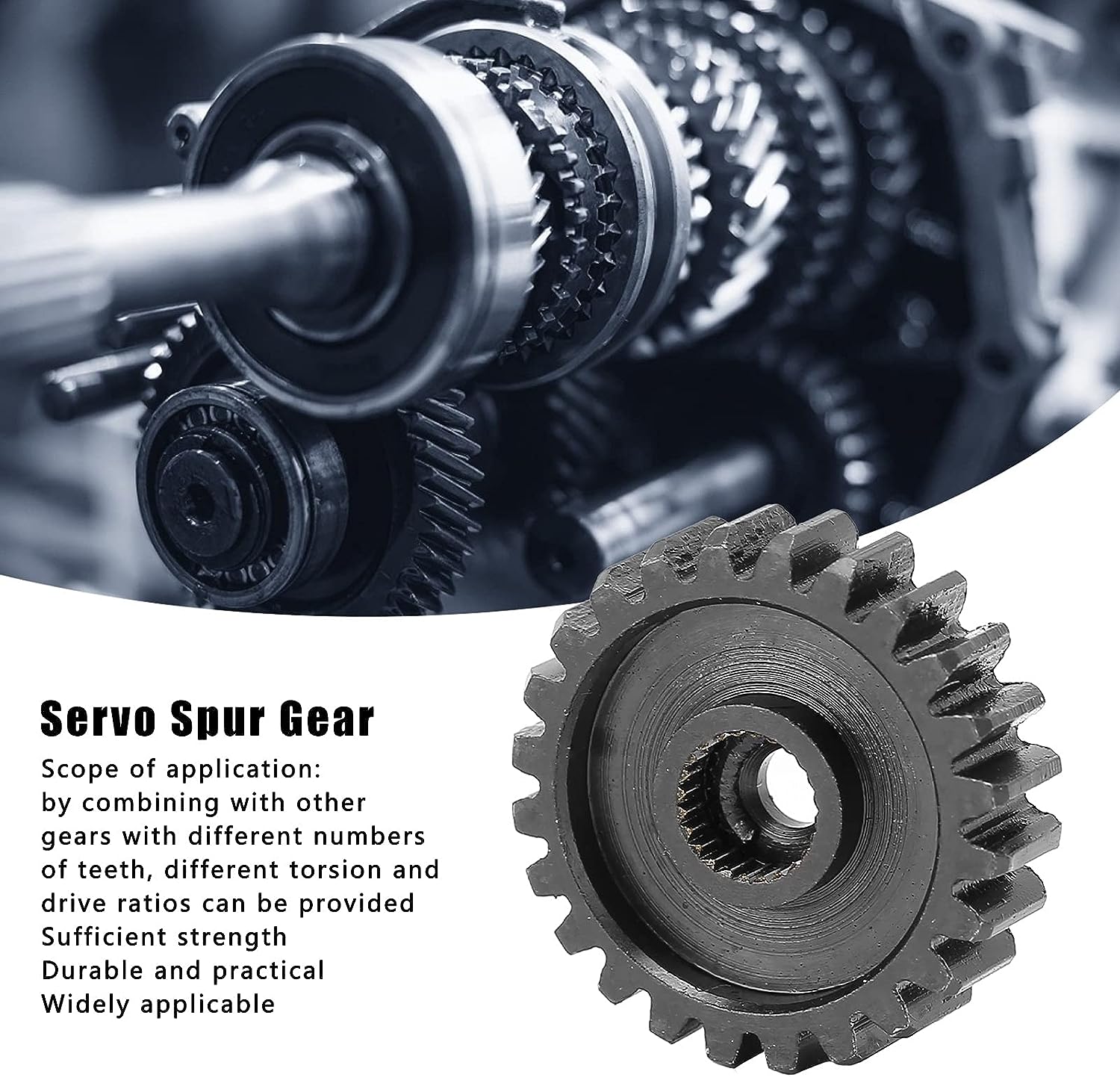
How do spur gears differ from other types of gears?
Spur gears, as a specific type of gear, possess distinct characteristics and features that set them apart from other types of gears. Here’s a detailed explanation of how spur gears differ from other types of gears:
- Tooth Geometry: One of the primary differences lies in the tooth geometry. Spur gears have straight teeth that are cut parallel to the gear axis. This differs from other gear types, such as helical gears or bevel gears, which have angled or curved teeth.
- Gear Meshing: Spur gears mesh by direct contact between their teeth, creating a line or point contact. This meshing arrangement is different from other gear types, such as worm gears or planetary gears, where the teeth mesh in a different manner, such as through sliding contact or multiple points of contact.
- Direction of Force: Spur gears transmit rotational motion and torque in a specific direction. The force is transmitted along the axis of the gears, making them suitable for parallel shaft arrangements. In contrast, other types of gears, such as bevel gears or hypoid gears, can transmit motion between non-parallel or intersecting shafts.
- Noise and Vibration: Spur gears tend to produce more noise and vibration compared to certain other gear types. The direct contact between the teeth and the sudden engagement/disengagement of the teeth can generate impact forces, leading to noise and vibration. In contrast, gear types like helical gears or double-enveloping worm gears provide smoother meshing and reduced noise levels.
- Efficiency and Load Distribution: Spur gears generally offer high efficiency in power transmission due to their direct tooth engagement. However, they may experience higher stress concentrations and load concentrations compared to other gear types. Gear designs like helical gears or planetary gears can distribute the load more evenly across the teeth, reducing stress concentrations.
- Applications: Spur gears find widespread applications in various industries and equipment. Their simplicity, ease of manufacture, and cost-effectiveness make them suitable for a wide range of systems. Other gear types have specific applications where their unique characteristics, such as high torque transmission, precise motion control, or compact size, are advantageous.
In summary, spur gears differ from other types of gears in terms of tooth geometry, gear meshing, direction of force transmission, noise and vibration characteristics, load distribution, and specific applications. Understanding these differences is crucial when selecting the appropriate gear type for a particular mechanical system, considering factors such as load requirements, motion control, efficiency, and design constraints.


editor by CX 2023-09-25